
Complete solution · AtoN House Nordic
Leading line
A leading line uses a front and rear light to indicate alignment with a specified approach axis.
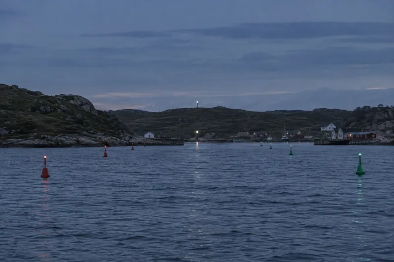
Commissioning verifies the status, alarms and controls supported by each connected instrument.
The components
Equipment
and interfaces
5 components with specified functions.
The labels identify their Emiko integration.
- 01Monitored through NaviGuard
Range lights
MSM MRL-M or MRL-D pair
Provides front and rear lights; PowerMonitor monitors current only unless a serial profile is confirmed.
Product page - 02Monitored through NaviGuard
Range lights
Tideland RLED-MasterRange pair
Alternative leading-light pair; specify the documented MasterRange Quad controller profile for NaviGuard.
Product page - 03Structure
Lattice masts
Two GMR masts, 2 to 24 m
Support the front and rear lights on designed foundations at the calculated positions and elevations.
Product page - 04Full Emiko integration
PowerGuard
PowerGuard at each position
Supplies each light and its controller; battery and solar capacity follow the separate site energy calculations.
Product page - 05Full Emiko integration
NaviGuard
NaviGuard at each position
Reports the specified serial profile or PowerMonitor current signal from each independently powered light site.
Product page
How it works
From the plan to the
commissioned installation
The approach geometry determines light positions and elevations. Optical and power requirements are confirmed for each position.
- 01
Define axis
The chart and survey establish the approach axis, channel width, viewing distances and observer heights.
- 02
Calculate geometry
The optical design establishes front and rear elevations, separation and required beam coverage.
- 03
Select lights
Select one front and rear pair for the day and night requirement; size both supplies including controller loads.
- 04
Align installation
The supports are installed and both lights are aligned; synchronisation is set where supported.
- 05
Record acceptance
Commissioning verifies the observed alignment, operating settings and supported Emiko status and alarms.
Where it is used
Approaches requiring a leading line
Port authorities, fairway operators and marine contractors specifying fixed guidance for an approach.
- 01
A harbour approach through shallow water
- 02
A narrow channel with a defined navigation axis
- 03
The final straight approach to a harbour entrance
Planning
Delivery scope
and equipment options
Delivered by Vikingegaarden
- Equipment specification from the marking plan, site data and operating requirements
- Component supply with the agreed manufacturer documentation
- Installation and commissioning, or technical support for the appointed contractor
- Emiko configuration and acceptance checks for supported equipment interfaces
- Service scope, inspection requirements and spare parts confirmed in the quotation
Good to know
Before the
quotation
What determines the separation of the lights?
Approach length, channel width, viewing positions and observer heights determine the geometry. The calculation establishes light separation and elevations for the required alignment sensitivity.
Can an existing structure support a light?
An existing tower or building may be suitable after checks of elevation, sight lines, structural capacity and mounting stability. The installation also requires power and maintenance access.
What is required for a quotation?
The enquiry requires the approach axis, chart or survey, channel width, observer heights, required day and night ranges, available mounting positions and power supplies.
Plan this solution
Project quotation
The specification defines the equipment, installation scope and price.
The enquiry requires a chart, positions, marking requirements, mounting details, available power and required autonomy.